KHL – Oil Level Controller
KHL Oil Level Controller (Single Switch for High/Low Level Alarm in Explosion Proof Enclosure)
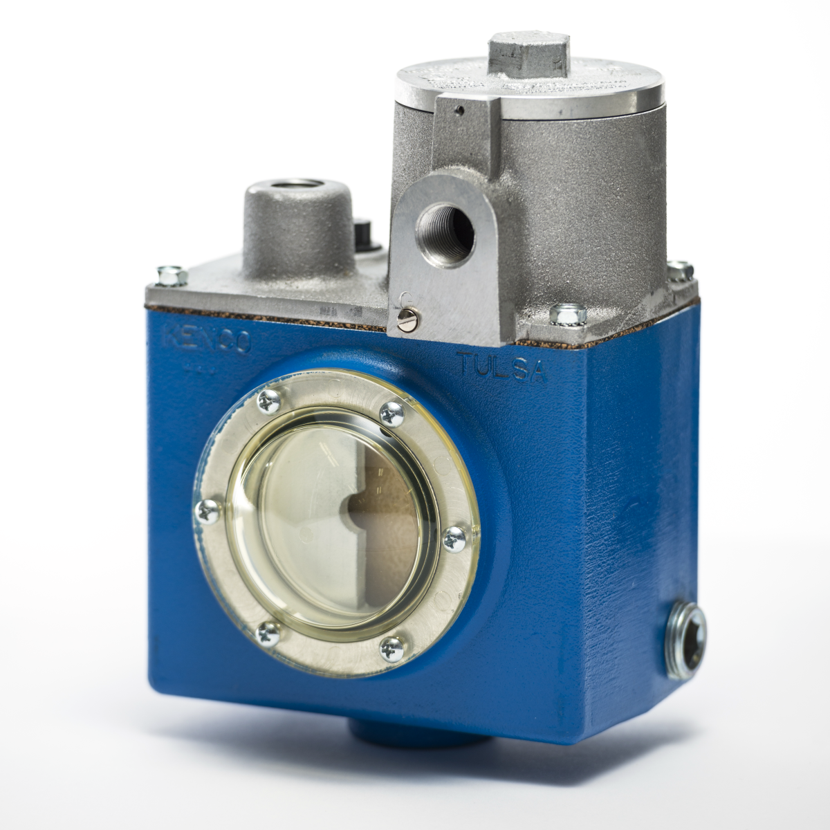
Operating Principle
KENCO Oil Level Controllers are designed to maintain the running oil level in the crankcase of stationary engines, compressors, and mechanical lubricator boxes. The KENCO oil controller works in conjunction with an overhead oil supply system which feeds the oil level controller. As the oil is consumed, the oil controller supplies the required amount of oil to maintain a proper level in the crankcase. The oil controller maintains the proper amount of oil in the crankcase by using a float controlled valve. The valve opens and closes as oil is needed in the crankcase to provide a constant oil level. The oil level switch in the KHL is an electric switch in an explosion proof enclosure, rated for hazardous hydrogen gas environments. The float switch monitors the oil in the crankcase. The level within the crankcase directly corresponds with the oil level in the oil level controller housing. If the oil level in the crankcase drops or rises 3/4″ past the centerline, the switch will trip sending an alarm.
Models Available
- KHL – Oil Level Controller with S.P.D.T. Electric Switch in Explosion Proof Enclosure for Single High Level and Low Level Alarm
- KHL-DPDT – Oil Level Controller with D.P.D.T. Electric Switch in Explosion Proof Enclosure for Single High Level and Low Level Alarm
- KHL-ES – Oil Level Switch with S.P.D.T. Electric Switch in Explosion Proof Enclosure for Single High Level and Low Level Alarm (No Oil Level Controller Function)
- KHL-ES-DPDT – Oil Level Switch with D.P.D.T. Electric Switch in Explosion Proof Enclosure for Single High Level and Low Level Alarm (No Oil Level Controller Function)
Applications
- Locations where high and low levels will be monitored by one alarm
- Hazardous locations where flammable or combustible elements are present.
- Stationary engines and compressors
- Mechanical lubricators
- Pumps
Features
- Reduces maintenance by maintaining a constant lube level.
- Protects against lubrication failure
- Controller mechanism fully removable without draining oil
- Easy view convex sight window
- High pressure applications up to 70 psig (4.82 bar)
- Fire Safe Valves Available
- Oil inlet allows for piping configuration from any direction
- Oil outlets on either side of housing and in the bottom to allow for various piping configurations
- Easy access to switch float through 3/8″ vent hole in top of housing for simple testing of switch operation
- Direct mount adapters eliminate equalizing problems and reduce installation costs
- Oil level controllers for synthetic oil applications now available
- CSA & ATEX Approved explosion proof switch enclosure
Specifications
Standard Materials of Construction
- Valve Seat – Buna-N
- Optional Valve Seat Material – Fluorocarbon
- Valve Orifice – Aluminum
- Housing – Aluminum
- Float Material – Closed Cell Polyurethane
- Oil Inlet Screen – 20 Mesh Brass Cloth
- Sight Window: – Transparent Nylon (UV Stabilized)
- Hermetically Sealed Glass (Optional)
Process Connections
- Oil Inlet Connection – 1/2″ FNPT
- Oil Outlet Connections – (3) 3/4″ FNPT
- Switch Conduit Connection – 1/2″ FNPT
Oil Inlet Data
- Static Head Pressure Range= 2-25 ft. / 0.86-9.5 psig (0-0.65 bar)
- Maximum Temperature= 180°F (82°C)
- High Pressure Models
- A= 10-35 psig (0.68-2.41 bar)
- B= 36-70 psig (2.48-4.82 bar)
Minimum Flow Rate Test Results
Standard Unit Tested at 32°F (0°C) with SAE 30
- 2′ head – 1.45 GPH
- 4′ head – 2.46 GPH
- 6′ head – 3.49 GPH
HP-A Unit Tested at 32°F (0°C) with SAE 30
- 10 PSIG– 4.09 GPH
HP-B Unit Tested at 32°F (0°C) with SAE 30
- 35 PSIG– 3.38 GPH
- 70 PSIG– 6.92 GPH
Electrical Switch Data
Switch Trip Point
- 3/4″ Drop
Switch Ratings
- 15 amp, 125/250/480 VAC
- 0.5 amp, 125 VDC
- 0.25 amp, 250 VDC
- 1/8 hp, 125 VAC
- 1/4 hp, 250 VAC
Maximum Temperature
- 180°F (82°C)
Electrical Connection
- 1/2″ FNPT
Standard Circuitry
- Single Pole Double Throw
Alternate Circuitry Options
- Double Pole Double Throw (KHL Only)
- High Level Switch
* CSA Approved Class I, Div.1, Div.2, Group B, C & D Hazardous Locations.
* ATEX Approved II 2 G EX d IIB + H2 T5
Mounting Adapter Options
- 1= Clark MA & CFA
- 2= Clark HMB & TMB
- 3= Clark RA, HRA, HBA, HCA, HLA, TCV & TLA
- 4= Ingersol-Rand SVG & KVS
- 5= Ingersol-Rand KVG
- 6= Cooper-Bessemer GMW
- 7= Cooper-Bessemer GMV
- 8= Cooper-Bessemer GMX
- 9= Universal Mounting Adapter
- 9MS= KLCE type housing with four 3/8″-16UNC integral mounting studs for use with -9 universal mounting adapter or any mounting configuration which incorporates the stud pattern
- Note: This option does not include the universal mounting adapter
- 10= Slotted Adapter for Universal Mounting
- 11= Mechanical Lubricator Mounting
- 12= Post Mount for 1/2″ Pipe
- 14= Cooper Superior Compressor (Formerly White)
- 15= Ingersoll-Rand XVG & PVG
- 16= Cooper-Bessemer BMV & 275 (Available with varied oil level)
- 17= Waukesha VHP Engines F2895, F3521, F5108, L5790 and L7042
- Replaces Inspection Door with Single Bolt Mounting Arrangement
- 18= Waukesha VHP Engines F2895, F3521, F5108, L5790 and L7042
- Same as -17 except with integral KENCO 1618 Low Flow Meter
- 19= Ingersoll-Rand Rotary
- 21= Cooper-Bessemer 2400 SERIES 6
- 23= Ariel KBC (2/4/6 Throw), KBD (2/4/6 Throw), KBF (2/4/6 Throw) Compressors
- 24= Ariel JGE (2/4 Throw), JGH (2/4 Throw), JGK (2/4 Throw), JGT (2/4 Throw), KBE (2/4 Throw), KBK (2/4 Throw) and KBT (2/4 Throw) Compressors
- 25= Ariel JGU (2/4/6 Throw), JGZ (2/4/6 Throw), KBB (4/6 Throw) and KBV (4/6 Throw) Compressors
- 26= Ariel KBU (2/4/6 Throw) and KBZ (2/4/6 Throw) Compressors
- 27= Waukesha VHP Engines F2895, F3521, F5108, L5790, L5794 and L7042
- Replaces Inspection Door with Two Bolt Mounting Arrangement
- 28= Waukesha VHP P9394GSI Engine with Standard Deep Sump Oil Pan
- Replaces Inspection Door
- 28S= Waukesha VHP P9394GSI Engine with Optional Shallow Oil Pan
- Replaces Inspection Door
- 37= Waukesha P9390 Engine
- Replaces Inspection Door
- 38= Waukesha P9390 Engine
- Same as -37 except with integral KENCO 1618 Low Flow Meter
- 39 = Waukesha P9390 Engine
- Same as -37 except with integral KENCO 14308 Low Flow Meter
- 40 = Waukesha VHP Engines F2895, F3521, F5108, L5790 and L7042
- Same as -17 except with integral KENCO 1618 Low Flow Meter
- 48A= Ariel JGB (4/6 Throw), JGC (2 Throw), JGD (2 Throw), JGF (2 Throw) and JGV (4/6 Throw) Compressors
- 48B= Ariel JGC (4/6 Throw), JGD (4/6 Throw) and JGF (4/6 Throw) Compressors with Standard Shaft Rotation and Single Chain Drive / Ariel JGC (6 Throw), JGD (6 Throw) and JGF (4/6 Throw) Compressors with Reverse Shaft Rotation and Dual Chain Drive
- 48C= Ariel JGC (4/6 Throw), JGD (4/6 Throw) and JGF (4/6 Throw) Compressors with Reverse Shaft Rotation and Single Chain Drive / Ariel JGC (6 Throw), JGD (6 Throw) and JGF (6 Throw) Compressors with Standard Shaft Rotation and Dual Chain Drive
- 991= Dresser Rand HOS, HOSS and MOS Compressors
- C33/34= Caterpillar C3300/3400 Engines
Additional Options
Electric Switch Option
- DPDT= Double Pole Double Throw Switch
Oil Inlet Pressure Options
- HPA= High pressure Oil Inlet, 10-35 psig (0.68 – 2.41 bar)
- HPB= High pressure Oil Inlet, 36-70 psig (2.48 – 4.82 bar)
Fire Safe Valve Option
- FS= Fire Safe Valves
- FSN50= Fire Safe Unit Supplied without 1/2″ NPT Fire Safe Valve
- FSN75= Fire Safe Unit Supplied without 3/4″ NPT Fire Safe Valve
Seal Option
- V= Fluorocarbon Seals
Sight Window Option
- GW= Glass Window
Hose Kit Option
- K= Hose Kit consisting of 6′ of 3/4″ I.D. Hose, (2) 1/2″ NPT Hose Barbs, (2) 3/4″ NPT Hose Barbs and (4) Hose Clamps
Test Button Option
- TB= Test button to allow for manual check of switch functionality
Synthetic Oil Option
Contact KENCO with Type and Specific Gravity of synthetic oil being used in the application

Installation Instructions
Spare Parts
Related Documents
Technical Drawings
-

KHL-ES-DPDT-9 -
KHL-ES-9 -
KHL-07 -
KHL-07-FS -
KHL-09 -
KHL-09-FS -
KHL-10 -
KHL-10-FS -
KHL-11-FS -
KHL-11 -
KHL-12 -
KHL-12-FS -
KHL-14 -
KHL-14-FS -
KHL-17 -
KHL-17-FS -
KHL-23 -
KHL-23-FS -
KHL-24 -
KHL-24-FS -
KHL-25-FS -
KHL-27 -
KHL-27-FS -
KHL-28 -
KHL-28-FS -
KHL-28S -
KHL-28S-FS -
KHL-48A -
KHL-48B -
KHL-48C -
KHL-991 -
KHL-DPDT-25-FS -
KHL-DPDT-25 -
KHL-DT-10 -
KHL-ES-09-FS -
KHL-ES-10-FS -
KHL-ES-10 -
KHL-ES-11 -
KHL-ES-12-FS -
KHL-ES-12 -
KHL-ES-14 -
KHL-ES-17 -
KHL-ES-24 -
KHL-ES-27 -
KHL-ES -
KHL-MS-09 -
KHL -
KHL-26 -
KHL-26-FS
