KPFS Pneumatic Float Switch
KPFS Pneumatic Float Switch
U.S. Patent 9,046,190 B1 & U.S. Patent 8,564,390 B1
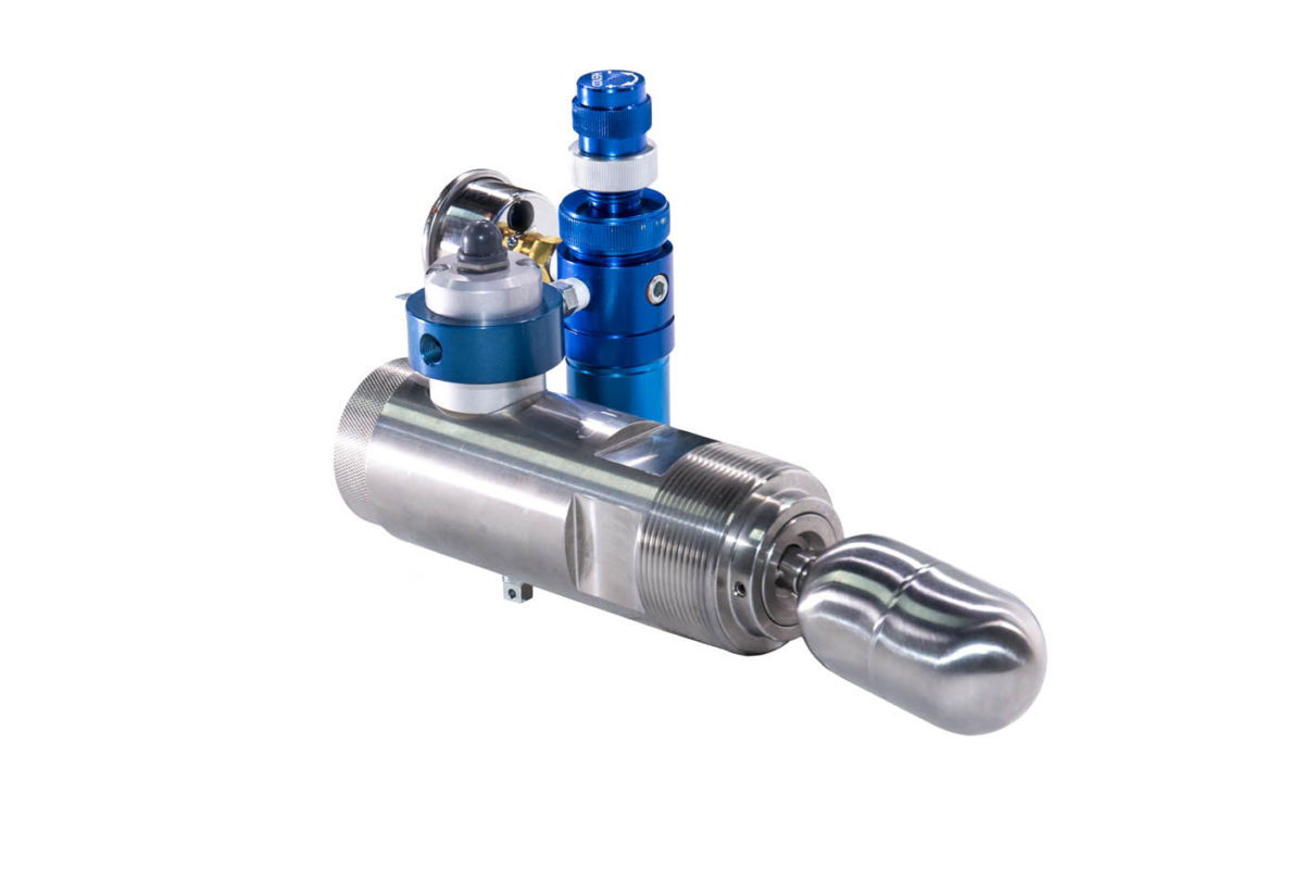
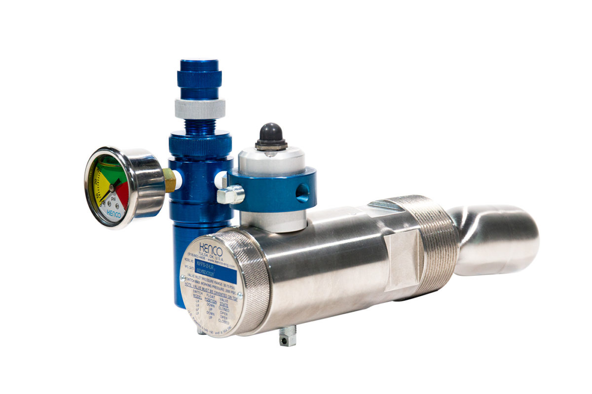
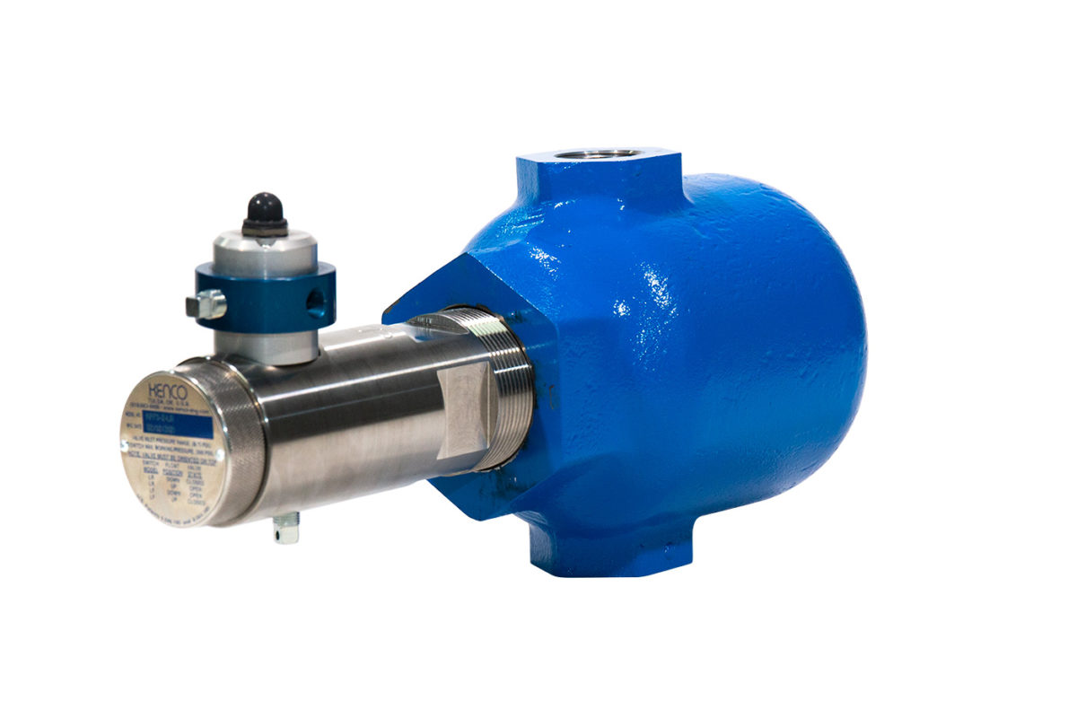
The KENCO Model KPFS uses a float to determine the presence or absence of liquid in a vessel at the process connection. The float arm assembly consists of a float at one end and a magnet at the other. As the level in the vessel rises, the float rises and the magnet falls. The magnet actuates a second magnet on the other side of the pressure boundary. This second magnet is the reactive component in the snap acting switch that opens and closes the pneumatic valve. Because of the nature of the design, adjustment is rarely, if ever needed. In the event that adjustment is needed, an easy to use adjustment screw is provided. The Model KPFS is used to actuate pneumatic dump valves, such as the Model KDV Series Dump Valve, to control liquids in scrubbers, separators and other vessels. The pressure boundary contains no seals; it is a solid stainless steel barrier that passes a magnetic field, but no liquids. It is impossible for the process liquid to enter the switch enclosure through this barrier. The Model KPFS Pneumatic Float Switch can be ordered to have the pneumatic valve open when it senses a liquid level rising (-LR option) or open when it senses the liquid level falling (-LF option). A manual valve actuator is provided to open the valve manually, if desired.
Features
- Simple Installation – Switch can be easily installed at the process connection in the vessel wall with simple hand tools.
- KFC External Float Chamber available for indirect switch vessel mounting
- Pneumatic valve pressure range of 30 to 75 psig (2.06 to 5.17 bar).
- Stainless Steel Body – All wetted parts including switch body are manufactured from 303/304 Stainless Steel.
- Stainless Steel Float – Float material is 304 Stainless Steel
- Sealless Switch Barrier – Magnetic switch actuator operates through a solid stainless steel barrier. There are no seals between the process and the switch compartment that could potentially cause a switch failure.
- Manual valve actuator provides a means to manually open the pneumatic valve.
- Optional filter/pressure regulator available to ensure supplied air or gas is filtered and regulated to improve system life and performance.
- Certificate of Authorization including CRN numbers issued for use in Canadian provinces and territories
Gallery
Specifications
KPFS Pneumatic Float Switch Specifications
| Description | Specification | |
| Specific Gravity | > 0.53 | |
| Wetted Parts | Standard | 303/304 Stainless Steel |
| Optional | 316 Stainless Steel | |
| Process Connection Size | Standard | 2″ NPT |
| Pneumatic Valve Connection Size |
Inlet | 1/8″ NPT |
| Outlet | 1/8″ NPT | |
| Exhaust | 1/8″ NPT | |
| Maximum Temperature Rating | 257°F (125°C) | |
| Process Pressure Range | Vacuum to 2000 psig (137.89 bar) | |
| Valve Inlet Pressure Range | 30 to 75 psig (2.06 to 5.17 bar) | |
* Note: The KPFS Pneumatic Float Switch requires clean, dry instrument quality air or gas. A pressure regulator with filter is available for improved valve life and trouble free operation.
Optional Pressure Regulator Specifications
- Maximum inlet pressure of 300 psig (20.68 bar)
- Maximum regulated outlet pressure range of 10 to 130 psi (0.68 to 8.96 bar)
* NOTE: Although the regulator is capable of regulating the pressure as high as 130 psi (8.96 bar), it must not be set any greater than 75 psig (5.17 bar). Factory setting on the regulator will be 0 psig. An adjustment knob and pressure gauge is provided with the regulator to allow adjustment of the regulator within the 30 psi to 75 psig (2.06 to 5.17 bar) range required by the pneumatic valve on the Model KPFS.
