KPRL Low Pressure Regulator
KPRL Low Pressure Regulator
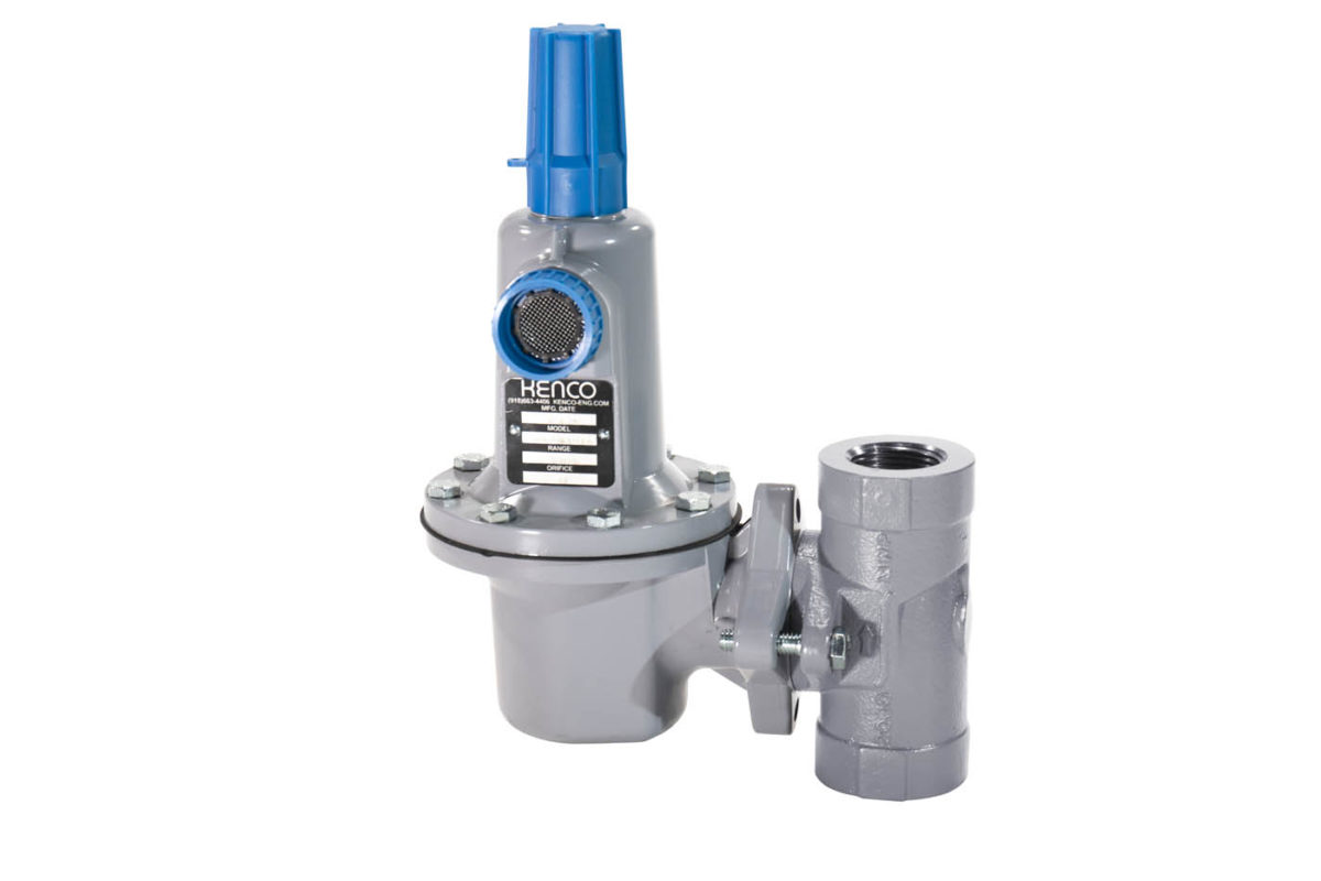
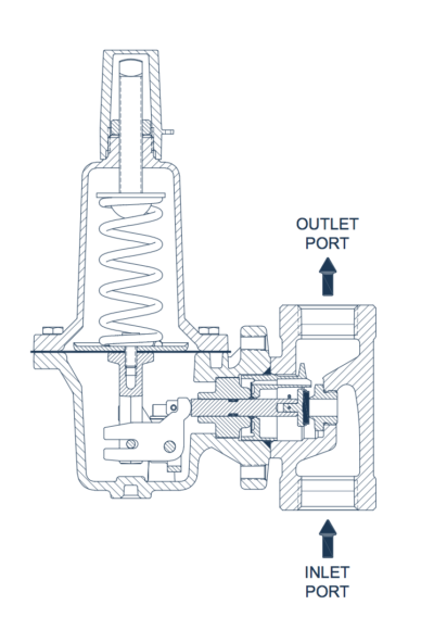
The model KPRL is a direct-acting pressure reducing regulator for use with natural gas, air, and a variety of other gases. The regulator outlet pressure is controlled by a diaphragm and an adjustable spring. As the downstream demand for flow changes, the downstream pressure changes. These pressure changes are registered by the diaphragm and will open or close the valve as needed to maintain the downstream pressure and flow requirements. There are five orifice sizes and five springs available to cover a wide range of application conditions. With the correct orifice and spring combination, the Kenco model KPRL Low Pressure Regulator will maintain a constant pressure downstream while meeting downstream flow requirements.
FEATURES
• 1” or 2” NPT, 1” or 2” 150 / 300 / 600 lb. raised face flanged process connections.
• 3/4” NPT vent connection with removable screened plug.
• Five different orifice sizes to accommodate a wide range of flow requirements.
• Orifice, seal holder, and valve stem all come standard in 316 Stainless Steel.
• Wear items can be replaced without removing the body from the piping setup.
• Carbon steel body rated for 2000 psi of inlet pressure.
• Diaphragm housing and spring housing constructed of sturdy die cast aluminum.
• Diaphragm housing and spring housing can be rotated in multiple orientations.
• Protective cap with UV inhibitor allows for tamper resistant pressure settings.
• 10 to 95 psi utility spring available.
• Wetted pressure retaining components on NPT models comply with
NACE MR0175.
APPLICATIONS
• Fuel Gas Scrubbers/Filters
• Separators
• Dehydration Systems
• Gas Gathering
• Farm Taps
• Flare and Burner Systems
OPERATING PARAMETERS
| Maximum Inlet Pressure |
Based on Spring Selection & Orifice Size / Seal Material |
|
Body Pressure Rating |
2000 psi |
|
150 Lb. Flange Rating |
285 psi at 100° F |
|
300 Lb. Flange Rating |
740 psi at 100° F |
|
600 Lb. Flange Rating |
1480 psi at 100° F |
|
Maximum Outlet Pressure |
Based on Spring Selection |
|
Maximum Diaphragm Housing Overpressure to Prevent Damage to Internal Components |
60 psi Above Set Point |
|
Maximum Diaphragm Housing Pressure to Prevent Leakage to the Atmosphere |
250 psi |
|
Maximum Diaphragm Housing Pressure to Prevent Burst |
375 psi |
|
Operating Temperature Ranges |
-20° F to 180° F |
Specifications
MAXIMUM INLET PRESSURES (PSI)
|
Outlet Pressure Range (Spring Color) |
Orifice Size | Nitrile Orifice Seal | Nylon Orifice Seal | FKM Orifice Seal |
Outlet Pressure Range (Spring Color) |
Orifice Size |
Nitrile Orifice Seal |
Nylon Orifice Seal |
FKM Orifice Seal |
|
*5-20 psi (Yellow) |
35-80 psi (Blue) |
||||||||
|
15-40 psi (Green) |
70-150 psi (Red) |
||||||||
|
10-95 psi (Black) |
When using the 10-95 psi (Black) spring, select the orifice size that falls within the application parameters described in this table. |
||||||||
ORIFICE SELECTION INSTRUCTIONS
Select the correct orifice size by comparing the wide open flow capacity at the application conditions to the desired ow rate. Calculate the ow rate (“Q”) through each orifice size using the Universal Gas Sizing Equation and Wide Open Flow Coefficients table below. Select the smallest orifice size that will meet the required flow rate needs. After selecting the orifice, make sure the application inlet pressure does not exceed the pressure rating listed in the Maximum Inlet Pressures table above.
PRODUCT SPECIFICATIONS
| Process Connection Sizes and Types |
1” or 2” NPT, 1” or 2” |
|
*Outlet Pressure Ranges and Spring Color |
|
|
Orifice Sizes |
1/8”, 3/16”, 1/4”, 3/8” or 1/2” |
MATERIALS OF CONSTRUCTION
|
Orifice Seal |
Nitrile, Nylon or FKM |
|
Diaphragm and O-Rings |
Nitrile or FKM |
|
Body |
ASTM A216 WCC Carbon Steel |
| Flanges |
ASTM A105 Carbon Steel |
|
Diaphragm and Spring Housing |
A380 Die Cast Aluminum |
|
Orifice and Seal Holder
|
316 Stainless Steel |
* Outlet pressure is factory set at the lower end of the specified outlet range.
Since inlet pressures are application specific, the startup outlet pressure may differ from the factory setting.
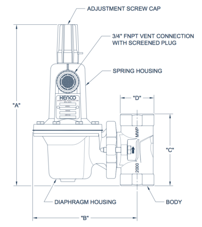
DIMENSIONAL INFORMATION
|
Process Connection Sizes and Types |
1” NPT |
1” 150 Lb. R.F. Flange |
1” 300 Lb. R.F. Flange |
1” 600 Lb. R.F. Flange |
2” NPT |
2” 150 Lb. R.F. Flange |
2” 300 Lb. R.F. Flange |
2” 600 Lb. R.F. Flange |
| A |
10-1/16” |
12-3/8” |
12-3/8” |
12-3/8” |
10-11/32” |
13-1/2” |
13-1/2” |
13-1/2” |
| B |
6-1/2” |
6-1/2” |
6-1/2” |
6-1/2” |
6-31/32” |
6-31/32” |
6-31/32” |
6-31/32” |
| C |
4-15/32” |
9-1/8” |
9-1/8” |
9-1/8” |
5-1/16” |
11-3/8” |
11-3/8” |
11-3/8” |
| D |
2-1/8” |
4-1/4” |
4-7/8” |
4-7/8” |
3-1/4” |
6” |
6-1/2” |
6-1/2” |
WIDE OPEN FLOW COEFFICIENTS
| Variables | Orifice | Cg | Cv | C1 |
|
1” NPT and |
1/8” |
16 | 0.51 |
30.6 |
|
3/16” |
33 | 1.03 |
32.0 |
|
|
1/4” |
54 |
1.88 |
28.7 |
|
|
3/8” |
112 |
3.24 |
34.6 |
|
|
1/2” |
193 |
6.27 |
30.8 |
|
|
2” NPT and |
1/8” |
15 |
0.52 |
29.6 |
|
3/16” |
34 |
1.05 |
32.4 |
|
|
1/4” |
51 |
1.95 |
26.2 |
|
|
3/8” |
113 |
3.49 |
32.4 |
|
|
1/2” |
205 |
6.48 |
31.6 |
Note: All flow coefficients were determined using lab tested data.
Important: The KPRL Low Pressure Regulator must always be used with overpressure protection. Use the Universal Gas Sizing Equation to select the appropriate relief valve.
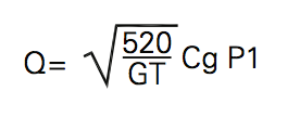
UNIVERSAL GAS SIZING EQUATION
Variables:
Q = Flow Rate (SCFH)
T = Gas Temperature @ Regulator Inlet (°Rankine) G = Gas Specific Gravity
P1 = Pressure @ Regulator Inlet (psia)
ΔP = Pressure Drop Across Regulator (psia)
Cg = Gas Sizing Coefficient
Cv = Liquid Sizing Coefficient
C1 = Flow Coefficient
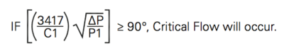
Equation to determine Critical Flow:
Flow Rate Equation for Non-Critical Flow Applications:
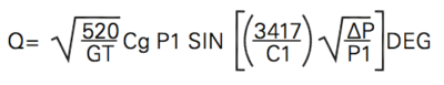
Flow Rate Equation for Critical Flow Applications: