KWR & KWT Weld Pad Level Gauges
KWR & KWT Weld Pad Level Gauges
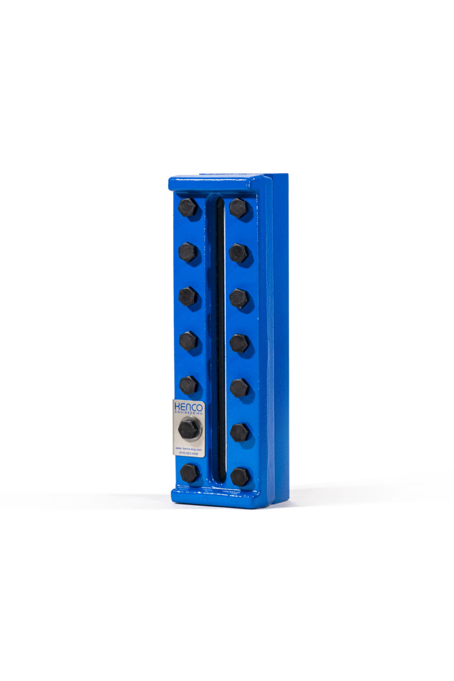
KENCO Weld Pad Flat Glass Gauges are used where direct visual observation of process fluids is required. This gauge style is designed to be welded directly to the vessel wall and is available with either reflex or transparent glass configurations. Transparent configurations can be provided with mica or Kel-F shields if needed. Multiple different ASME approved material options are offered for the wetted chamber. All materials meet or exceed ASTM standards to withstand even the most demanding application requirements. In addition to the different material options offered, the gauge chamber can also be supplied with an optional machined radius to match the curvature of the vessel when required.
There are five main components to all flat glass gauges:
- Chamber: Center of the gauge, and is the part that primarily contains the process fluid. It is machined from bar stock. The gasket seat is recessed for lateral support, and easy positioning.
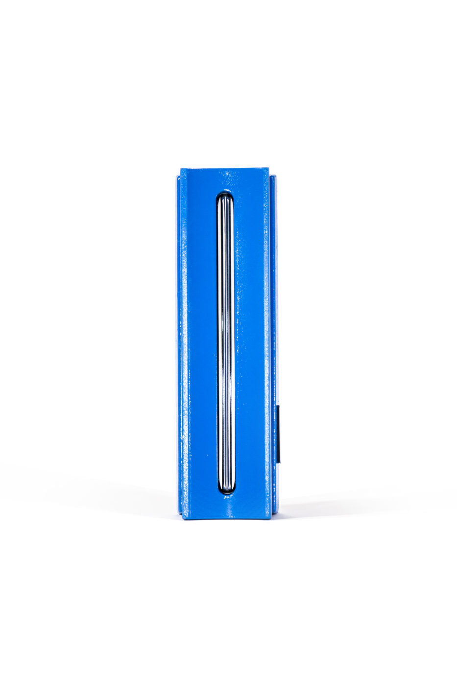
- Glass: Provides the visual interface between the process fluid and the outside.
- Cover: Protects the glass, and provides the compression surface for sealing the gauge. The cushion seat is recessed for lateral support and easy positioning.
- Gasket/Cushion: Provides for a seal between the chamber and glass (gasket), and protects the glass from mechanical stresses from the cover (cushion). For a given gauge, the gasket and cushion are normally the same material.
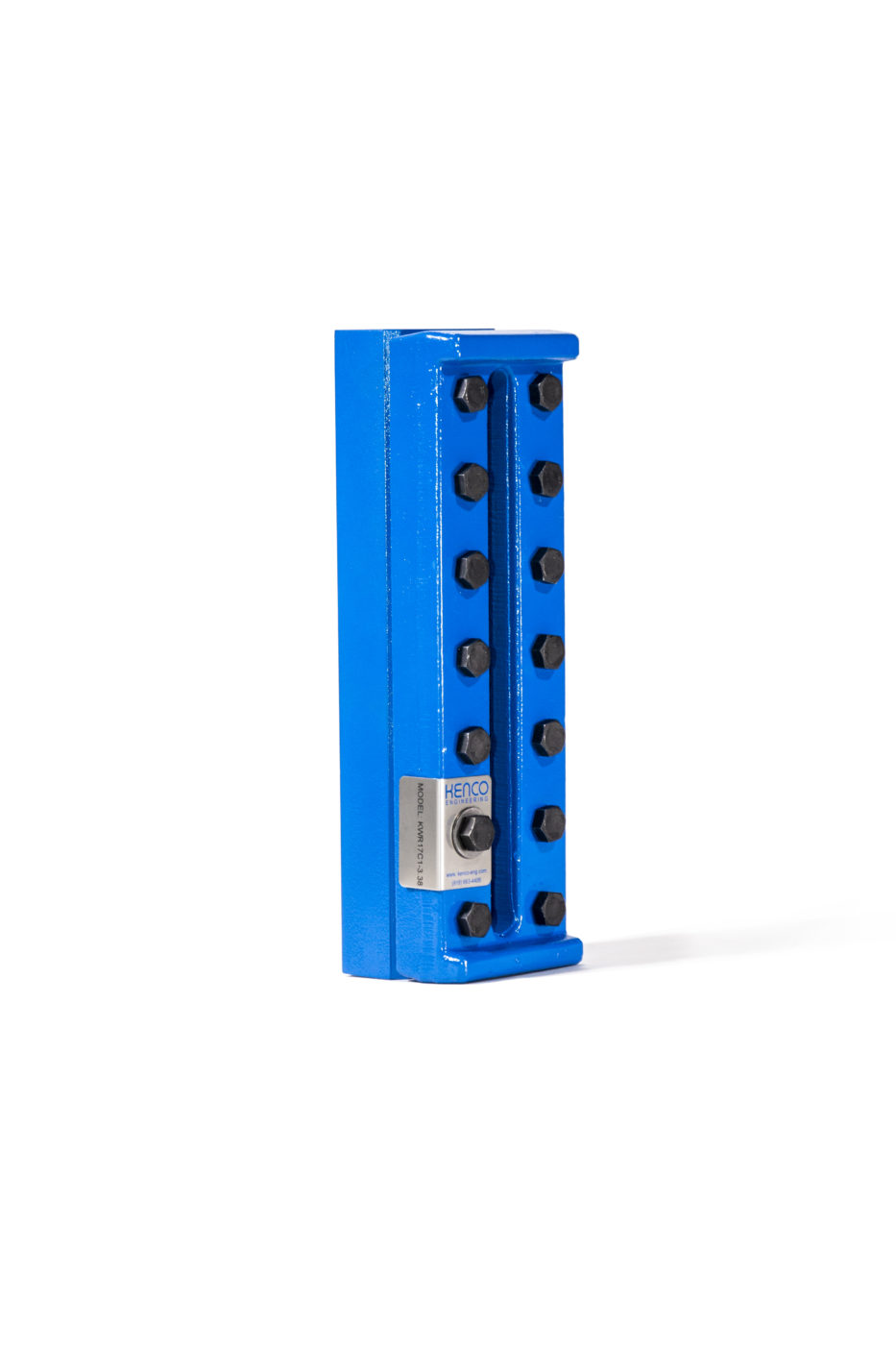
- Bolts/Studs: Provides a uniform compression load to the gauge for pressure sealing.
Weld Pad Style Level Gauge Ratings
Standard KENCO Weld Pad gauges will withstand the pressure loads inside the gauge itself but are not designed to replace the strength lost in the wall of the vessel where the slot or holes are cut. The Gauge design is suitable for applications up to 750°F (398.8°C).
Other Features
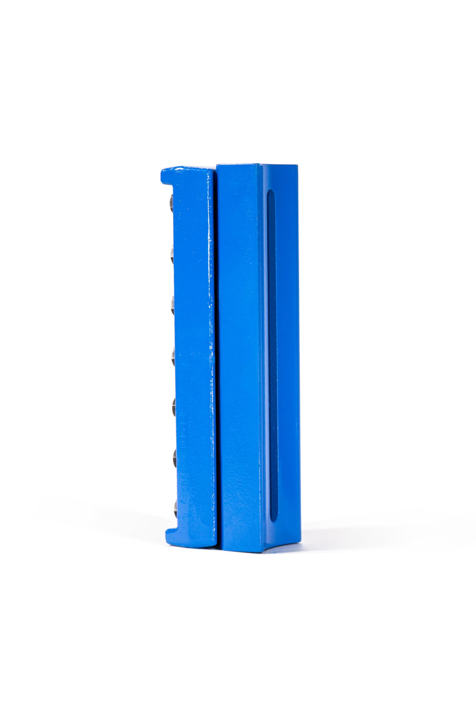
- Chamber visual length can be supplied either fully slotted or with 2 holes and a channel
- Fully slotted chamber allows viewing of viscous liquids and liquids with solids with no piping to clog
- Available with Reflex and Transparent style glass configurations
- Kel-F and Mica shields available with Transparent style glass models
- ASME approved materials to meet most application requirements
- Vessel matching radius machining available in chamber upon request
- Optional steel spacer available to reduce the risk of warpage to the gasket surface during welding
- Temperature rating from -150oF to 750oF (-101°C to 398.8°C)
- All forged components produced entirely of USA Origin materials
Other Gauge Accessories
Frost Proof Extension
The KENCO Frost-proof Extension is used in low temperature applications where frost has a tendency to build up on the gauge. This extension prevents frost from covering the window, maintaining visibility at all times. The Frost-proof Extension consists of clear, plastic block that is in direct contact with the glass, and extends beyond the cover so that frost build-up does not block the glass. Mounting is easy, and can be added to any Reflex or Transparent gauge in the field. The extension can be installed or removed for cleaning while the gauge is in service.
Gauge Glass Options
KENCO supplies tempered borosilicate glass as standard in all Flat Glass Gauges. Borosilicate glass is suitable for most chemicals, and is good for temperature ranging from -425°F to 600°F (218.3°C to 315.5°C) – glass rating only. The tempering process improves the thermal shock resistance of the glass. Aluminosilcate glass is offered as an option for higher temperature applications. It offers less thermal expansion, as compared to borosilicate glass. Aluminosilicate glass is good for temperatures ranging from -425°F to 800°F (218.3°C to 426.6°C) – glass rating only. However, due to the added cost, it is only recommended for applications with temperatures from 600°F to 750°F (315.5°C to 398.8°C).
Glass Shields
For corrosive or steam applications, KENCO offers shields to extend the life of the glass in Transparent gauges. The shields are made from either PCTFE (Kel-F) or Mica. Mica shields are recommended for steam service. Kel-F shields should be used in corrosive fluid applications. The shield is placed on the process side of the glass. Shields can only be used with Transparent gauges.
Gauge Scales
Gauge scales can be supplied to provide a numerical reference to the level being measured. Contact KENCO for more information.
Gallery
Specifications
Gauge Type
- KW = Weld Pad
Gauge Style
- R = Reflex
- T = Transparent
Gauge Sections
- 1 – 4
Glass Size
- 1 – 9
Materials of Construction
- A1 = 316 S.S. Chamber, 316 S.S. Cover Without Shield
- A2 = 304 S.S. Chamber, 316 S.S. Cover Without Shield
- C1 = A36 C.S. Chamber, A350 C.S. Cover Without Shield
- C2 = 1018 C.S. Chamber, A350 C.S. Cover Without Shield
- C3 = A516 C.S. Chamber, A350 C.S. Cover Without Shield
- W1 = 316 S.S. Chamber, A350 C.S. Cover Without Shield
- W2 = 304 S.S. Chamber, A350 C.S. Cover Without Shield
- K1 = 316 S.S. Chamber, 316 S.S. Cover With Mica Shield
- K2 = 304 S.S. Chamber, 316 S.S. Cover With Mica Shield
- L1 = A36 C.S. Chamber, A350 C.S. Cover With Mica Shield
- L2 = 1018 C.S. Chamber, A350 C.S. Cover With Mica Shield
- L3 = A516 C.S. Chamber, A350 C.S. Cover With Mica Shield
- M1 = 316 S.S. Chamber, A350 C.S. Cover With Mica Shield
- M2 = 304 S.S. Chamber, A350 C.S. Cover With Mica Shield
- G1 = 316 S.S. Chamber, 316 S.S. Cover With Kel-F Shield
- G2 = 304 S.S. Chamber, 316 S.S. Cover With Kel-F Shield
- H1 = A36 C.S. Chamber, A350 C.S. Cover With Kel-F Shield
- H2 = 1018 C.S. Chamber, A350 C.S. Cover With Kel-F Shield
- H3 = A516 C.S. Chamber, A350 C.S. Cover With Kel-F Shield
- J1 = 316 S.S. Chamber, A350 C.S. Cover With Kel-F Shield
- J2 = 304 S.S. Chamber, A350 C.S. Cover With Kel-F Shield
Chamber Visual Configuration
- H = Two Hole (Recommended For Reflex Glass)
- S = Fully Slotted (Recommended For Transparent Glass)
Optional Machined Radius (To Match Vessel Curvature)
- 2.00″ – 12.00″
