KSF Cast Body Sight Flow Indicators
KSF Cast Body Sight Flow Indicators
Application
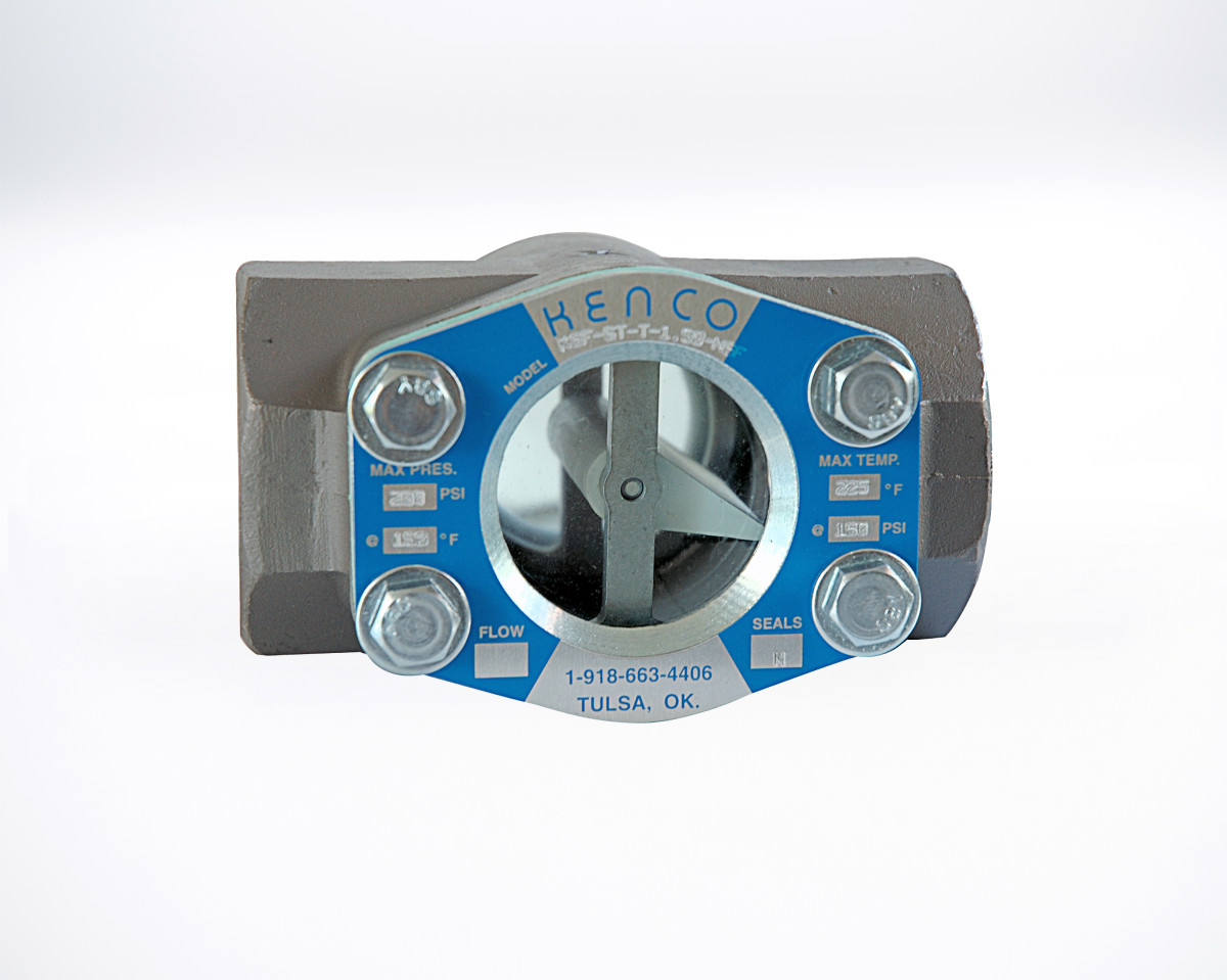
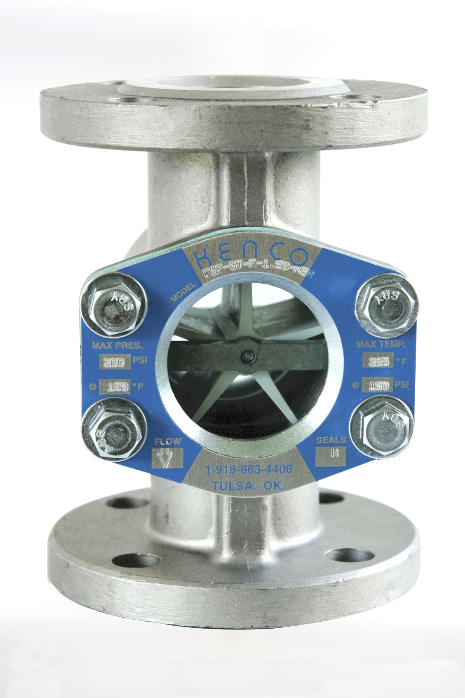
KSF Cast Body Sight Flow Indicators have a heavy duty cast construction to handle pressure and temperature requirements. A glass window on either side provides product visibility. Mechanical indicators to enhance the visibility of the media include flappers, rotors, and drip tubes. The cast body and threaded or flanged connections meet ANSI standards. Standard materials of construction are carbon steel, 316 SS, ductile iron, and bronze. Hastelloy C 276 and alloy 20 can also be supplied. Please consult the factory for pricing. The KSF Sight Flow Indicators are available in two series – ST and HT. The ST series is designed for standard temperatures and pressures while the HT series is designed for higher pressures and temperatures. Please see specifications for exact ratings of each.
Product Features
No Leak Design
The radial sealing method and the bolt-on body design provides years of service with no torquing maintenance required.
ANSI Rated
The cast body and the threaded or flanged connection meet ANSI standards. Flanged models conform to standard ANSI mounting dimensions; threaded models are provided with standard NPTF threads. All flanged units are supplied with 150# R.F. flanges. The 2″, 3″, and 4″ can be supplied with 300# flanges.
3 Year Warranty
All KSF sight flow indicators are guaranteed free from defects in material and workmanship for 3 years from date of shipment. If a unit fails within the first 3 years, Kenco will supply replacement parts or replace the unit at our expense. 
Plain
Unit may be mounted in any direction and flow is bi-directional. Used to indicate easily visible fluids or lack of same to detect color clarity of turbulence of fluids.
Flapper
Units may be mounted either horizontally or vertically with upward flow. These units are used with clear fluids.
Rotor
Unit my be mounted in any direction. Right to left flow is standard. Specify if left to right flow is required. Rotor is highly visible. The units are designed for clear, translucent or dark fluids. Standard rotor material is Delrin. PTFE is available as an option.
Drip Tube
Units are designed for vertical application only with downward flow. They are recommended for intermittent gravity or extremely low flow rates.
Gallery
Specifications
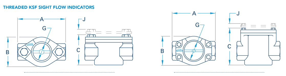
Threaded KSF Sight Flow Indicators
| Indicator Size (Inches) | 0.25″ | 0.35″ | 0.5″ | 0.75″ | 1″ | 1.25″ | 1.5″ | 2″ |
| A Overall Length | 3.25 (1) | 3.25 (1) | 3.25 (1) | 4.25 (2) | 4.25 | 5.25 (3) | 5.25 (3) | 5.50 (3) |
| B Overall Width | 2.00 | 2.00 | 2.00 | 2.56 | 2.56 | 3.31 | 3.31 | 3.31 |
| C Overall Height (ST Series) | 2.38 | 2.38 | 2.38 | 3.25 | 3.25 | 4.31 | 4.31 | 4.31 |
| Overall Height (HT Series) | 2.56 | 2.56 | 2.56 | 3.44 | 3.44 | 4.50 | 4.50 | 4.50 |
| G Sight Opening Diameter | 1.13 | 1.13 | 1.13 | 1.50 | 1.50 | 2.00 | 2.00 | 2.00 |
| J Added Height Due to Shield | 0.44 | 0.44 | 0.44 | 0.50 | 0.50 | 0.50 | 0.50 | 0.50 |
| Weight (pounds) | 1.60 | 1.60 | 1.40 | 3.00 | 2.70 | 8.40 | 7.90 | 6.60 |
(1) 316 SS Units are 3.63″; (2) Bronze Units are 4.13″; (3) 316 SS Units are 5.63″
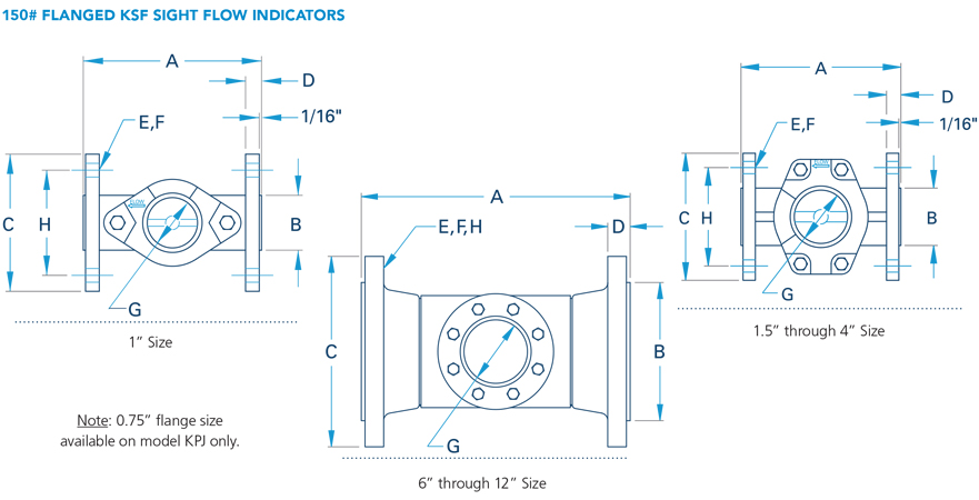
150# Flanged KSF Sight Flow Indicators
| Indicator Size (Inches) | 1″ | 1.5″ | 2″ | 3″ | 4″ | 6″ | 8″ | 10″ | 12″ |
| A Overall Length | 5.00 | 6.50 | 7.00 | 8.00 | 9.00 | 14.25 | 16.13 | 16.13 | 17.13 |
| B Raised Face Diameter | 2.00 | 2.88 | 3.63 | 5.00 | 6.19 | 8.50 | 10.63 | 12.75 | 15.00 |
| C Flange Diameter | 4.25 | 5.00 | 6.00 | 7.50 | 9.00 | 11.00 | 13.50 | 16.00 | 19.00 |
| D Flange Thickness | 0.47 | 0.59 | 0.69 | 0.81 | 1.00 | 1.00 | 1.13 | 1.19 | 1.25 |
| E Number of Bolt Holes | 4.00 | 4.00 | 4.00 | 4.00 | 8.00 | 8.00 | 8.00 | 12.00 | 12.00 |
| F Bolt Hole Diameter | 0.63 | 0.63 | 0.75 | 0.75 | 0.75 | 0.75 | 0.75 | 0.88 | 0.88 |
| G Sight Opening Diameter | 1.50 | 2.00 | 2.00 | 3.00 | 3.00 | 4.00 | 4.00 | 4.00 | 4.00 |
| H Bolt Circle Diameter | 3.13 | 3.88 | 4.75 | 6.00 | 7.50 | 9.50 | 11.75 | 14.25 | 17.00 |
| Weight (pounds) | 5.40 | 11.10 | 15.00 | 29.30 | 35.00 | 85.00 | 125.00 | 165.00 | 250.00 |
Technical Data
| Pressure/Temperature Ratings | ||
| KSF | Max Pressure | Max Temperature (1) |
| ST Series (Flanged/Threaded) 1/4-4″ ST Series (Flanged) 6″-12″ HT Series (Threaded) HT Series (Flanged) Carbon Steel HT Series (Flanged) 316SS HT Series (Flanged) Ductile Iron |
200 PSIG @ 150°F 150 PSIG @ 150°F 400 PSIG @ 150°F 285 PSIG @ 100°F 275 PSIG @ 100°F 245 PSIG @ 100°F |
250°F @ 135 PSIG 150°F @ 150 PSIG 400°F @ 160 PSIG 400°F @ 195 PSIG 400°F @ 195 PSIG 400°F @ 195 PSIG |
(1) With Standard Seals
| Seal Material Temperature Ranges | ||
| Seal Material | Minimum | Maximum |
| Neoprene (standard ST series) Fluorocarbon (standard HT series) Buna-N EPDM PTFE Kalrez |
-20°F -20°F -20°F -50°F -40°F 0°F |
250°F 400°F 212°F 250°F 400°F 500°F |
Threaded KSF Sight Flow Indicators
150# Flanged KSF Sight Flow Indicators
Style Designation
- KSF-ST = Standard Temperature Model
- KSF-HT = High Temperature Model
Connection Types
- F= Flanged
- T= Threaded
Connection Sizes for Flanged Models
- 1.00″
- 1.50″
- 2.00″
- 3.00″
- 4.00″
- 6.00″
- 8.00″
- 10.00″
- 12.00″
(*) Not available in 12″ size
Connection Sizes for Threaded Models
- 0.25″
- 0.375″
- 0.50″
- 0.75″
- 1.00″
- 1.25″
- 1.50″
- 2.00″
Seals
- V= Fluorocarbon
- N= Neoprene
- T= Teflon®
- B= Buna-N
- E= EPT
- K= Kalrez
- HTT= Teflon® – High Temperature to 500°F (260°C)
Body Material Options for Flanged Models
- C= Carbon Steel (*)
- S= 316 Stainless Steel
- A20= Alloy 20
Body Material Options for Threaded Models
- C= Carbon Steel
- B= Bronze
- S= 316 Stainless Steel
- A20= Alloy 20
Shield Options
- NSH= No Shield
- SH= Shield
Flow Indicator Styles
P = Plain
Unit may be mounted in any direction and flow is bi-directional. Used to indicate easily visible fluids or lack of same to detect color clarity of turbulence of fluids.
F = Flapper
Units may be mounted either horizontally or vertically with upward flow. These units are used with clear fluids.
R = Rotor
Unit my be mounted in any direction. Right to left flow is standard. Specify if left to right flow is required. Rotor is highly visible. The units are designed for clear, translucent or dark fluids. Standard rotor material is Delrin. PTFE is available as an option.
D = Drip Tube
Units are designed for vertical application only with downward flow. They are recommended for intermittent gravity or extremely low flow rates.
